


US$ 1,170.00
ex. VAT, ex. delivery costs
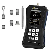
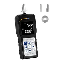

The force gauge is a handy, digital measuring device for measuring tensile and compressive forces. The force gauge offers a sampling rate of 500 Hz and various measurement options such as real-time measurement (RT), maximum value measurement (PEAK), configurable average value acquisition (Average) and automatic measurement storage of up to 100 measurements.
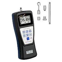
The force gauge is a handy, digital measuring device for measuring tensile and compressive forces. The force gauge offers a sampling rate of 500 Hz and various measurement options such as real-time measurement (RT), maximum value measurement (PEAK), configurable average value acquisition (Average) and automatic measurement storage of up to 100 measurements.
For quick, easy and accurate force measurements, manufacturers rely on PCE’s force gauge products. A force gauge is a valuable tool used to measure product performance, safety and quality as well as compliance with industry standards. A force gauge also is used to evaluate the physical and mechanical properties of raw materials and components during product research, development, design, manufacturing, production and assembly. Thus, a force gauge has many uses including but not limited to testing of plastics, packaging, paper, medical devices, electronics, fabric, textiles, springs, wires, electrodes, welds, metals and material composites.
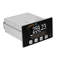
A force is usually visible only when it causes changes. We do not see the force though, but its effect. However, this effect is not only dependent on the height and direction of the force, but also on the influences that counteract the force. In order to be able to determine and compare forces objectively, various methods and devices for measuring forces have been developed. In a force gauge with an analogue display, a pointer is usually moved along the scale by the force to be measured.  The force gauge with a digital display shows the measured values as a graph or numerical value on the electronic display. Many of these devices can also store the measured data available in the electronic form or transmit it directly to computers or other devices via interfaces.
The internationally used unit for force is the newton. It also applies to the weight force caused by the gravity. In everyday life, in medicine and also for load specifications, however, the term weight is usually used with the specifications in the unit kilogram and other forces are also specified in kilograms. For this reason, there are many models of force gauges that display the measured values in grams or kilograms. In the Anglo-American language area, the force reference is indicated by an appended f for force, where it is not kg but kgf. A force of one kilogram (kg or kgf) corresponds to about 10 (9.81) newtons and one newton to about 100 (102) grams.
The measuring range, the display steps and the measuring accuracy depend on the measuring principle and the force transducer used. For example, a digital force gauge of a certain model series can measure from 0.000 to 5.000 Newton with a resolution of 0.001 Newton and another force gauge of the same model series can measure up to 100,000 Newton with a resolution of 10 Newton.
The force gauge can be destroyed by the forces that are too high, but also by incorrect loading with the wrong force application point, wrong force direction or by additional dynamic loads that have not been taken into account. The magnitude and direction of the forces and whether they can be safely absorbed and evaluated by the measuring device therefore play an important role in the selection of the device. In addition, it must be taken into account that many of the devices only function reliably if certain operating conditions are observed. For some applications there is a large selection of different types of devices, but for the others only a few device variants come into question or special adaptations or special solutions have to be developed for the individual case.
How do you determine what force gauge is best suited to your application? The following text is designed to help you make an informed purchasing decision.
- What type of force testing system does your application require (e.g., portable handheld force gauge or force gauge with stationary force test stand or universal testing machine)?
- What type of force need to be measured (e.g., compression, tension, torque, peel strength, flexure / bend strength, etc.)?
- What is the anticipated minimum and maximum force to be measured (e.g., force measuring range of 0 ... 500 N)?
- What degree of accuracy is necessary for the successful completion of your force testing task?
- What memory size and data transfer interface is needed, if any?
- What level of after-sales service and support is desired?
- What is your budget?
Following is a more detailed analysis of criteria to keep in mind when selecting a force gauge.
The answer to this question largely depends on the intended application. If you want to use the force gauge to sporadically collect readings for quality assurance, a portable force testing device should be used. If you want a more precise and repeatable force test, it will be better to use a stationary force test stand with your force gauge. In addition to providing stability, a stationary force test stand, also called a universal testing machine (UTM), can be equipped with an RS-232 interface or USB port, allowing the test stand to be controlled by a computer.
When selecting a force gauge, one must consider how the force is initiated. Tension is the pulling force, whereas compression is the pushing force. Both tension and compression are common forces measured by a force gauge. When testing peel strength, the force is initiated by adhesion. Flexure / bend strength is a test performed primarily on coatings to assess formability, ductility and elongation. Another common force measurement is torque. Torque is the force initiated by rotation. For torque measuring instruments, visit torque meters / torque testers.
For safety reasons, you must choose a force gauge that accommodates the maximum force to be measured. Then, a buffer should possibly be taken into account, if the required measuring accuracy permits it. In addition, hazards that may arise during the force measurement should be determined and eliminated accordingly beforehand. For example, if during a tensile force measurement, there is a risk that the test material could get twisted, the force measuring device must be secured by means of a clamp to prevent injury.
For applications requiring minimal force, a simple and cost-effective force measuring device is a spring scale. A spring scale measures weight or force, typically in grams (g), kilograms (kg), pounds (lbs) and / or Newtons (N), when an object is hung from the hook of the scale. Also called a spring balance, this mechanical force measuring device is ideal for physics force experiments and for teaching action-reaction in science, technology, engineering and math (STEM) classrooms and other educational settings. During measurement, the spring installed in the scale is extended or pulled. When released, the spring returns to its original state.
Another force measuring device with a mechanical measuring principle is a hydraulic force gauge. A hydraulic force gauge uses a hydraulic liquid to measure acting forces. Hydraulic force sensors are designed for much larger force measuring ranges in comparison to spring scales. However, the disadvantages of hydraulic force gauge devices are lower measuring accuracy, lower measuring resolution and lack of measurement traceability. For these reasons, digital force gauge devices are predominantly used.
A digital force gauge consists of two important components: the sensor and the meter or evaluation unit. In digital force gauge devices with lower measuring ranges, the sensor is often installed internally. For larger measuring ranges, the sensor is connected externally to the meter. Many digital force gauge products are multi-purpose and will measure both tension and compression forces, among other parameters such as rotation speed and triaxle vibration. There is no one sensor that could be suitable for all measurement tasks. Thus, these multi-purpose digital force gauge devices will often come with adapters and / or be programmed to perform mathematical measurement conversions.
An important parameter for a digital force gauge is the maximum possible sampling rate. Sampling rate is the frequency with which the transmitter checks the force sensor. 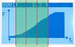 It is often indicated as an Hz number. 1000 Hz means that the force sensor is queried 1000 times per second by the transmitter, and the transmitter is able to change the measurement data 1000 times per second. Low cost force gauges have only one sampling rate of 2 Hz which is sufficient for a slow force measurement but is definitely unsuitable for a tear test. Because of the slow reaction, many measurement data of the force influence during the tear test are lost and that is why are not meaningful.
The user is not able to process an enormous amount of data (1 kHz = 1000 Hz = 1000 values per second) during the measurement. So, here it also must be considered whether the evaluation system / transmitter is able to provide the user in any form with 1000 values. Thus, the measurement data can subsequently be evaluated individually. Some low cost transmitters of the force measurement can query the sensor, e.g. 1000 times, but are not able to provide the user with the data sufficiently and in the fullness, since the processing electronics is unable to process the measurement data at that speed. Then, the average values are calculated which are then passed further.
Another popular, albeit expensive, force measuring tool is a highly flexible resistance strain gauge (DMS). A DMIS is a thin film to which a wire pattern or measurement grid is adhered. This wire is supplied by an external voltage and changes the resistance or conductivity due to expansions and compressions. This change is so far proportional and reproducible that an external evaluation indicator can carry out the calculations of the force. These DMS films are then attached (glued) to the measuring points where the deformation can be recorded with the help of the measuring grid. However, it must still be taken into account that there are other influencing factors such as temperature, humidity, magnetic fields, etc., that can affect the conductivity and thus distort the readings. Just as in the finished force sensors the DMS films are easily placed at those places of the construction where the force exerts the greatest deformation. However, it must, by all means, be considered, that the DMS strips must have a fixed connection to the ground so that to give the deformation further. Thus DMS strips cannot be used again after they have been glued once.
The higher the maximum load of the sensor, the lower the measuring accuracy of the sensor. Thus, a compromise should be reached here. Each force gauge will have its own accuracy specifications that are dependent upon the range being measured. Typically a higher accuracy measuring instrument will come with a higher price tag, so it is important to consider practicality as well as precision.
Whether for a long-term or for a short-term measurement, in both cases, the data analysis is elementary. The data can be processed due to the special functions of the evaluation system / transmitter and provided to the user. 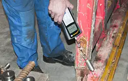 If the user wants to determine, e.g., only the maximum force, the transmitter can present the highest value in the form of PEAK or MAX from the collected data (note sampling rate) and filter out the other readings. If the user still wants to determine the other reading such as, e.g., the average value, then possibly another function and filters are necessary.
In the best case, the whole collected measurement values after the force test can be stored. These raw files allow even later to determine the desired results from the already carried out measurement experiments. So there is an evaluation system / transmitter from the force measurement which stores the measurement data in the internal memory and can provide the data to the user after the measurement. Another way to save the measured data is to transfer the data to a storage device such as a PC or data logger using an RS-232, USB, 4-20 mA or 0-10 V interface.
This is another important point to keep in mind. Find out how long the supplier has been in business. The longer the company's tenure, the more likely it is that you will be able to order spare parts a few years down the road after buying your force gauge. PCE Instruments has been in business since 1999. (For more details, please visit the About Us / Corporate History section of our website.) Also find out what kind of technical support will be available to you. Call PCE Instruments, talk to the technical support team prior to purchasing and see for yourself the level of service provided.
Often more is involved in the budget than just the cost of the force gauge. Calibration costs are common expenses that can occur when using a force gauge. For instance, if you need to meet the requirements of an ISO quality standard, a regular calibration interval needs to be adhered to. ISO calibration costs can occur at the time of purchase and reoccur on an annual or even semi-annual basis, depending on your accuracy needs and usage of the force gauge. It is also possible that recalibration becomes necessary later on, due to the drift that sensors can experience over time. Consumables like (rechargeable) batteries should be included in your calculations as well.
For robust weighing equipment, please visit the crane scales and heavy-duty scales sections of the PCE Instruments website.
Generally speaking a Force Gauge is a device used to measure the applied compression or stretching force (push / pull) or to define the moment of force (torque). Depending on the type such device allows to detect the force in the range from hundredth of kN to MN.
There are mainly two kinds: mechanical and digital ones.
A resilient element in the mechanical is a spring or lever. The force influences the spring and the latter is either compressing or stretching. The lever gauge is less accurate, the lever is deformed as a result of the force application. The weak point of the mechanical gauges is their dependence on the temperature and the inaccurate reading by the human eye.
In their turn, the mechanical devices can be of three kinds: Force gauges for general purpose – devices for measurement of the stretching force of class I and II, meant for operation in the rooms from -5° to +35° (II class) and from – 5° to +45° (I class) and relative humidity not more than 80%.  Another kind is waterproof, which means the device can operate at relative humidity not more than 98 %. The third kind of compression and stretching Force Gauge is sample-like – meant for calibration of the measuring means at the laboratory.
An electronic force gauge is widely used in the automotive industry and transport, in the production of the automated technological systems or for mechanisms verification. The main element in the electrical force gauge is a strain gauge transducer which is used as a resilient element, measuring unit with the indicator and the connection cable. Different kinds of sensors can be used in the electrical gauges which widens the sphere of their application.
These force measurement devices give much more accurate results, as there is also a cable allowing to transmit the data to the computer and process it digitally. The electronic devices transform the deformation of the resilient element into the electrical signal. For example, these devices are used to measure the force of compression of the automatic doors in the transport, garage, gate …
In medicine the portable, handheld device is necessary to measure the muscle force of the hands. It is often used in the medical and sport institutions, sanatoriums etc. There are special devices for children, as children muscle force which is different in the housing shape and size. These force gauges allow to make conclusions about the general physical shape of the patient. It is absolutely necessary on the rehabilitation stage as it helps to control how the body is developing after trauma. Compression model is required to measure the static compression force during the inspection test benches and machines.
Another application field is gas and oil production. Such devices can give signal about emergency loads, generate and print reports and test instruments. The duration of tests is shown on their displays with an accuracy of second.
A Force Gauge is often used to measure the tensile force of ropes during the test of the seal strength of anchors when fixing braces in the process of installation and repair of drilling rigs systems.
For the laboratory experiments and tests of new equipment the electronic models with the microprocessor control are used. These force gauges can be mounted on test stands.
A Force Gauge finds its application there where it is difficult to imagine it could be used, for example, there is a special Egg Force Reader a device which helps to measure the level of force necessary to break a shell of an egg. When using that device it is possible to find out the best ways of transportation and marketability of the product.
A Force Gauge is very often used for testing how string the floor is. This can be really an important issue at the factories or industrial rooms where it goes about heavy loads. A wide range of tests can be carried out in the process of production with the help of this device. Depending on the component parts of the force gauge different kinds of that device can be used in the testing, construction, production of goods, engineering, factories etc.
Also the Force Gauge is used in the chemical and textile industry. This device is priceless when it goes about checking how strong the fabric or fragile the material is. One of the important branches in animal breeding is down production. To make the production profitable it is necessary to guarantee the good quality product, which means, appropriate length, softness, strength, weight etc and etc. Force Gauge is applied to check the strength of the down.
In reality there can be dozens of examples when the force test instrument is applied, including automotive, medical, packaging, production areas.
Force gauge for testing wires and ropes
Wires are long thin metallic rods with a constant mostly round cross-section, while ropes consist of several natural or synthetic fibre cords or wires twisted together. Wires and ropes perform important load-bearing or transmission functions in many areas. There are areas of application with the rigid wires or ropes as well as with the wires or ropes that move according to the plan. 
Whether on high-voltage lines or overhead railway lines, on buildings, bridges, cable cars, lifts, cranes or other machines, tests before and after installation are intended to ensure that wires and ropes can fulfil their functions safely. New ropes are tested before the installation with a tensile testing machine or with a suitable force gauge in special fixtures. ISO 2307:2019 and EN ISO 2307:2019 and based on it DIN EN ISO 2307: 2019-12 "Fibre ropes – Determination of some physical and mechanical properties" specify, among other things, the methods for measuring the breaking force and elongation of the rope under tensile stress.
For tensile force measurements on the tensioned wires or ropes, a mobile force gauge specially designed for the rope force measurement can be used, which is set up so that the rope is guided on three rollers of the gauge. These special rope tension meters are available for different force ranges, rope diameters and with different lengths of the measuring distance. However, free access and sufficient space for mounting the measuring device are always required. If space is limited, the force gauge with a ring-shaped force transducer or a rope clamp can be used. These are also suitable for continuous monitoring of the forces on the installed rope.
Force gauge for testing spring forces
Technical springs are elastic components that deform under load and return to their original shape when the load is removed. The best-known forms include tension, compression and torsion springs formed from spiral spring wire, but also flat springs and spring clips. Springs are used for a wide variety of applications. The dimensions, shape and load capacity of the spring can be precisely adapted to the requirements of the application.
With a force gauge for testing spring forces, it is possible on the one hand to determine what force is necessary to achieve an intended deformation of the spring. On the other hand, a suitable force gauge can also be used to determine the range in which the deformation changes proportionally to the applied force. Within this range, the springs themselves can also be used to measure forces. With the spring constant or spring hardness determined from force and travel, the applied force can be calculated for each deformation of the spring or displayed on a suitable scale.
Often, the force gauge for measuring spring forces is integrated into a fixture that can be used to ensure the repeatable test conditions. Some of these load test stands also allow load cycle endurance tests on safety-relevant springs, the failure of which would have significant consequences. Whether on machinery, vehicles or equipment, correctly dimensioned and long-lasting springs are a prerequisite for smooth functioning or easy operation in many places, e.g. pressure switches, pedals and seat belts.
Force gauge for "peeling tests”
The term “peeling” stands for the flat peeling off of thin layers. In a peel test, the force gauge is used to test under specified conditions how much force is required to remove a film or other thin covering layer from the substrate. There are different methods, but the prerequisite for the peel test is always that the cover material reacts sufficiently flexibly to bending and can be lifted off as a layer.
In the case of the peel tests on packaging, it is often a question of ensuring that the packaging, e.g. for perishable foodstuffs, medicines and sterilised medical products, is tightly sealed but can also be opened again with a reasonable amount of effort. In the case of durable materials, on the other hand, the top layers should adhere as permanently as possible to the substrate, e.g. on floor coverings, doors or furniture. With some safety and protective films or adhesive tapes, it is also important that they can be easily removed from the substrate without leaving any residue, despite good adhesion.
Many composite materials, but also the adhesion of lids on the food packaging such as yoghurt cups, are tested by fixing the sample and lifting the top layer at an angle of 90 degrees, 180 degrees or 45 degrees to the substrate. In contrast, the adhesive strength of two thin superimposed layers, such as in the stretch films or pressed, welded or glued seals, is determined in the so-called T-peel test. In this T-peel test, the two films are pulled evenly in opposite directions. The force gauge suitable for the peel test can usually be clamped into the force measuring stands or fixtures where it is guaranteed that the speed and the direction of pull are maintained. In most test cases, the force gauge should not only display the maximum force, but also the force progression over the duration of the test. In the case of the product tests, this can also be used to determine the uniformity of the bonding and sealing.
Pedal Force Measurement
Just as per pedes means on foot, a pedal is a lever moved with the foot. Pedals are often used to operate certain functions on devices, machines, vehicles or musical instruments with the feet. The force applied to the pedal with the foot can be transmitted directly or after amplification or attenuation. Here, very different effects can be triggered with the pedals. In the motor vehicles, for example, separate pedals are used for accelerating, clutching and braking. On the machines, the pedals can also be used as safety or trigger switches. The force exerted by the operator's foot on the pedal to change the position of the pedal is called the pedal force. The forces required to achieve the desired effect can be determined with a pedal force gauge. If the specified values are not met, the pedal must be readjusted or replaced.
In the German guideline for testing the brake systems of vehicles during main inspections (HU) according to § 29 StVZO from 24 May 2012, the values for the minimum braking and the maximum permissible actuating forces for this are specified for various vehicle types. For passenger cars and motor homes weighing less than 3.5 tonnes, a maximum of 50 kilograms (or decanewtons) of force applied to the brake pedal should result in the desired braking deceleration. For buses, trucks, tractors and motor homes weighing more than 3.5 tonnes, the maximum force should be 70 kilograms (or decanewtons).
Since the safety of the machines and vehicles should not depend on the physical strength of the user, the pedals are nowadays designed in such a way or their action is reinforced so that no great force is required to operate them. This is ensured by the brake boosters or the pneumatic brake systems. Appendix 2 of the HU Brake Directive describes a procedure that also uses the pedal force gauges to check hydraulic brake systems. In other European countries it is already compulsory to also determine the pedal force during the mandatory brake inspection. In Austria, for example, the inspectors have had to measure the pedal force required for the maximum achievable braking effect on the wheel since January 2020. The measured value must then be compared with the manufacturer's reference values.
Force measuring device for testing door and gate forces
Despite well-known negative examples and updates of accident prevention regulations, there are still accidents with personal injury at inadequately secured doors and gates.  This mainly concerns power-operated doors and gates, including revolving doors, swing doors and gates, sliding doors and gates, as well as all types of vertically closing gates such as overhead, sectional and rolling gates.
The closing forces must be limited for all power-operated doors and gates that are not fully secured by dead man's controls, safety edges attached to the closing edge or contactless protective devices such as light barriers. This is checked by the trained experts with the suitable force measuring device. DIN EN 16005 and DIN EN 12453 define the measuring conditions and the limits for the level of the static and dynamic forces and their duration of action. The force measuring device used for testing the closing forces must therefore not only be able to record the maximum height but also the temporal course of the acting force.
The requirements for the force gauge specified in DIN EN 18650 Part 1 Paragraph 6.2.2 include:
- The force must be applied via a round measuring surface with a stiffness of 500 N/mm².
- The measuring frequency must be at least 200 Hertz over 5 seconds.
- It must be possible to measure forces from 25 N to 2,000 N.
- The measuring accuracy must be at least ±5 percent in relation to the measuring range.
In addition to safety, the operability of the doors in everyday use plays an important role. Modern doors that meet special requirements for sound, heat and fire protection should be easy to open and close despite these functions. Particularly in the case of buildings for the public and those intended for a user group with physical limitations, care must be taken to ensure that the operating forces of the doors also comply with the standards for the barrier-free buildings.
The abbreviation ASTM stands for American Society for Testing and Materials. The international standardization organization ASTM International is based in the USA and works with the experts from 150 countries to develop and update the standards for increasing safety and product quality. By standardizing product properties and test procedures, the standards also help to facilitate international trade.
For many products and materials, both ASTM standards and EN standards exist. The specifications for the respective product tests differ in some cases. To avoid misinterpretation, the test results must therefore be clearly labelled. If a force gauge is used for the measurements according to different standards, it should be possible to clearly identify the applied standard in the stored measurement results. If the force gauge does not allow a distinction, the user is responsible for correctly assigning the measured values.
The current approximately 13,000 ASTM guidelines are divided into different areas, which are indicated by capital letters:
Guidelines for force and torque measurements and the requirements for the force measuring instrument used for these measurements are grouped into the respective sections according to their applicability. The following sections provide examples of some of the ASTM standards for stress tests.
CAUTION!
Some ASTM test methods list values in both inch-pound units and SI units. These may not be simply converted to the other, as the underlying test specifications may differ, for example, in the material thickness of the sample. Inch-pound units are the units still widely used in the Anglo-American language area and thus also in the USA. SI units are the metric units specified in the International System of Units.
ASTM E8 / E8M Standard Test Methods for Tensile Tests on Metallic Materials
Describes test methods for testing the tensile strength of metals. The standardized specimens are clamped and subjected to uniaxial tensile loading at room temperature.  If, in addition to tensile strength, elongation and yield point and other material-specific values are to be determined, the test arrangement must permit control of the test speed and the force gauge used must be capable of accurately recording not only the applied tensile force but also the strain with a sufficiently large number of the measured values.
ASTM A370 Testing of Mechanical Properties of Steel Products
Includes not only tensile, but also bending, stiffness, and hardness tests for various steel products.
ASTM D412 Tests for Vulcanized Rubber and Thermoplastic Elastomers
Defines conditions for the measurements of tensile load and elongation behavior. These include tests for tensile load and elongation determination at break, tensile load measurement at specified elongation, and determination of permanent length change of elastic materials after loading. The force gauge and the device for applying the tensile force are to be selected in such a way that the elongation distance is large enough and a uniform elongation rate is guaranteed.
ASTM D638 Testing of Tensile Strength of Plastics
Covers test methods for determining the tensile strength of unreinforced and reinforced plastics up to 14 mm thick at the same pretreatment, temperature, humidity, and testing machine speed. Specimens less than 1 mm thick should be tested in accordance with ASTM D882 whenever possible. The test results include the tensile force that can be applied until failure of the material, the tensile modulus, the change in length when the specimen fails, and the ratio of elongation to thinness of the material tested.
ASTM D1000 Test Method for Pressure Sensitive Coated Adhesive Tape Used in Electronic Applications
Deals with testing the adhesion strength and support to steel at low temperatures and room temperature, adhesion strength after immersion in solvent, tensile strength and elongation at low temperatures and room temperature, twisting, dielectric breakdown stress, puncture resistance, and relaxation force at room temperature and low temperatures. To determine what force is required to loosen or damage the tape, the force gauge with appropriate equipment is required.
ASTM D1002 Testing the Strength Properties of Metal Adhesives in the Tensile Shear Test
Describes a method for determining the shear strength of adhesives used for bonding metals. Since such adhesives are also used in the automotive, aerospace, and electronics industries, the strength of these bonded joints is of great importance to the functional safety of the components involved.
ASTM D1621 Testing the Compressive Properties of Solid Foams
Provides not only compressive strength but also calculation of compressive strain and modulus of elasticity from the results of the tests. To accomplish this, the test fixtures and force gauge must allow for a constant loading rate and compression of the specimens to 13 percent of their original height. The guideline requires a measurement accuracy of one percent for the measuring devices used.
ASTM F1566 Testing of innersprings, box springs, mattresses or mattress sets
Describes test methods for comparing the durability and fatigue strength of mattresses regardless of their material. For this purpose, loads are applied that simulate body movements. To ensure that the test results are comparable, the type and level of loads are precisely specified.
ASTM D5034 Test Method for Test Tear Force and Elongation of Textile Fabrics (Grip Test)
Contains various grip test methods by which breaking strength and elongation of many textile materials can be determined. These also include wet tests. They are suitable for woven fabrics, nonwovens, and felts, but should not be used for glass fabrics, knitted fabrics, and other textile materials with more than 11 percent elongation.
Other ASTM standards for tests on textile materials requiring the use of an appropriate force measuring device are ASTM D5035, ASTM D1294, ASTM D2256, ASTM D2261, ASTM D2653, ASTM D2731, ASTM D3787, ASTM D3822, ASTM D4884, ASTM D4964, ASTM D6241, ASTM D6775, ASTM D7269, and ASTM D8054.
ASTM Standards with Torque Measurement
Torques of certain magnitude are often required to secure bolted joints or for expansion anchors. The amount of torque often has to be limited both upwards and downwards. Only then it can be ensured that the connection is held securely by the clamping force and is not destroyed.
The tightening torques for compression fittings are governed by the standards depending on the type of fitting:
ASTM A193, ASTM A307, ASTM A320, ASTM A325, ASTM A354, ASTM A449, ASTM A490.
If bolted connections are secured by adhesive bonding, the resistance of the bond can be checked according to
ASTM D5649 - Torque Resistance of Adhesives Used on Bolted Fasteners.
Additional requirements apply to the screws for use in the body, for example, for fixation of bone fractures.
ASTM F543 - Cortical bone screws – defines important requirements. In addition, there are a number of other internationally recognized ASTM guidelines for implants that must absorb or transmit forces. These include
Screw caps on containers can be secured so that they cannot be opened by small children because of the force required. Since some products, such as tablets or other medicine, are intended to be child-resistant but still accessible to physically impaired persons, special securing principles are used there. Procedures and conditions for testing torque and supplemental threaded fasteners are described in:
ASTM D2063, ASTM D3198, ASTM 3472, ASTM D3810, ASTM 3968 and ASTM D7860.
Torques are checked not only on bolted connections with the force gauge. The torques occurring under certain operating conditions can also be determined on rotatably mounted machine parts. For example, it is possible to determine how the behavior of lubricants at low temperatures affects the torque. Regulations on this are formulated in ASTM D1478 for ball bearings and in ASTM D4693 for wheel bearings.
Force measurements are performed in a wide variety of applications. For some applications, a force gauge with standard equipment is sufficient, such as for simple tension or compression measurements with the balances. For other force measurements, however, special accessories are needed to hold the specimen or apply the force. For frequently occurring applications, such accessories are often already available with suitable mounting options for the force gauge or force stand. Various manufacturers stock a wide range of clamping devices for fixing specimens and also a large number of adapters for applying forces.
However, more specialized tasks cannot be easily implemented with the measuring technology offered in the standard program. For these cases, an existing force measuring device can possibly be adapted or extended to meet the specific task, or suitable sensors and evaluation devices can be combined with additional components to form a suitable measuring device. In the delivery program of PCE Instruments there are several force measurement solutions which have been developed in cooperation with the customers for their tasks and which are now also available for other customers.
These include:
Other solutions developed specifically to meet the needs of individual customers include:
In the case of coated wood-based panels, special edge bandings are often bonded to the cut edges. These are not only intended to protect the board against damage to the edges and moisture penetration. The edge protection also serves to enhance the appearance and prevent someone from injuring themselves on the cut edge and damaging clothing or other material.
Various problems can occur during bonding, resulting in a lack of adhesion between the board and the edging material. PCE Instruments, in cooperation with the company Rehau, has developed a measuring device with which the adhesive strength of edge bonding can be tested easily, quickly and with a reproducible procedure. This allows random samples of product batches to be tested directly in production.
The measuring device, with dimensions of just 490 mm x 210 mm x 150 mm, enables a 90-degree peel test to be run automatically after clamping the end of the test edge. For this purpose, the force gauge was mounted on the housing so that it can be moved. The feed rate is defined at 50 mm per second and the travel distance at 100 mm. A force gauge with a maximum force of 500 N was selected for the intended application.
During the peel test, the tested chipboard piece is pulled over the ball rollers arranged on the surface of the housing at a 90 degree angle to the direction of pull with almost no friction. The self-locking clamping jaws and the smooth-running guide rollers for the edging material ensure that the test procedure runs safely. Experienced users need less than one minute for a complete measurement including preparation.
During the test procedure, the force gauge stores individual values from which the minimum, maximum, difference between minimum and maximum and the average of the tensile force are shown directly on the display. Two settings are possible for the number of the measured values, either 10 or 40 individual measurements per second. Detailed evaluations of the measurement process are possible with the aid of the device-specific PC software, which can also display the data as a force-time diagram.
Forklift attachments with large-area clamps are often used for the safe transport of large electronic appliances such as refrigerators, stoves, washing machines. The clamp arms have several adjustment points via which the clamping force can be adapted to the load. Since the forces on the clamp cannot be displayed, a device should be developed to measure the clamping forces generated by the adjustments.
The PCE-4PCFM force measurement stand, developed by PCE Instruments especially for this task, simultaneously measures the applied compressive forces at four different measuring points. 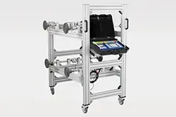 The device is designed for a maximum force of three thousand kilograms per measuring point and displays the measured values with a resolution of one kilogram.
This force measuring stand can be used to test various large-area clamps quickly and reliably. The position of the measuring points on the equipment trolley can be easily changed for this purpose by moving them. For an uncomplicated change of the test location within workshops or warehouses, the test stand has been equipped with a rechargeable battery and castors.
In this force test stand, each test can be linked to an identification number for the tested part. The data can be printed or stored on a USB flash drive and used for comparison the next time the large area clamp is tested. To simplify the adjustment of the clamps, it is possible to specify the target values for the total force and the individual measuring points. Deviations in the measurement results are then highlighted in color on the display.
It is important to set the correct clamping force on the gripper arms so that the objects held do not slip or are not damaged by pressing too hard. The four-point force measuring stand developed and manufactured by PCE Instruments is now successfully used by the customer. The force measuring stand enables fast and precise measurement for four clamping points simultaneously. As a result, the large area clamps can now be controlled and adjusted to the desired values much more easily.
Miniature force transducers - features and application
Miniature force transducers are force sensors that are characterized by particularly small dimensions. Due to their small size, it is possible to integrate them into machines, production plants and test setups without high adaptation efforts, even where little space is available. Therefore, miniature force transducers are often used for force measurements to monitor and control industrial processes and when testing new materials and components.
The size of the miniature force transducers does not allow any conclusions to be drawn about the measuring range. They can be designed for low or for high forces. A load cell with a housing diameter of 25 millimetres, for example, can be used either for forces up to 50 Newtons or up to 5,000 Newtons, depending on the measuring cell installed. Depending on the type of the load cell, static or dynamic measurements for compression or tension or both force directions are possible.
A prerequisite for the use of the miniature load cell is that the force to be measured can be introduced in a targeted manner. Therefore, there are different designs for miniature load cells with different versions for force transmission. Many types are disc or cylinder shaped. However, there are also designs as tension rods, bending beams, force washers or in S-shape. The force can be applied directly via contact surfaces or via screw threads, holes or eyelets.
To ensure that the miniature force transducer does not fail immediately in the event of an unplanned load, models with overload protection and high lateral load insensitivity have been developed. For applications where additional forces act transversely to the direction of the measurement, it is essential to select the miniature force transducers with sufficient lateral load stability. These force transducers are designed in such a way that the measuring cell is not destroyed by the applied lateral forces and is not influenced during the recording of the force to be measured.
The connection cable for the voltage supply and the signal output is also usually arranged at a ninety-degree angle to the direction of the force in the miniature force transducer. As with other sensors, these cables differ not only in length but also in the number of cores. The body and cable are usually so robust that neither normal operating materials nor moisture can damage them. This ensures high reliability even in demanding environments.
Hydraulic force transducers – types and their applications
The terms hydraulic and hydraulics are composed from the Greek words "hydro" for water and "aulos" for tube. They are used in engineering to refer to closed systems that use the properties of fluids to transmit forces, signals and energy. Special hydraulic oils are used instead of water in many applications.
Hydraulic force transducers measure compressive forces in such a way that the applied forces push the hydraulic fluid onto a spring body and cause it to move in the structurally specified direction. The stronger the applied force is, the more the spring is pressed. In this way, the pressure can be measured and displayed without auxiliary energy.
In addition to the completely analogue models with scale display, there are many hydraulic force transducers with digital displays or interfaces. There, the pressure value is converted by transmitters into electronic signals for digital displays or standard interfaces. The analogue devices can only additionally display the highest value of the measurement series by means of a drag pointer that is moved along until it is zeroed again. Hydraulic force transducers with transducers, on the other hand, can also be equipped with an electronic measurement value memory.
Hydraulic force transducers are frequently used to determine the compressive forces on machines. Analog models are suitable, for example, for individual measurements for setting up and adjusting the forces on machine tools, presses, clamping devices and hoists. They can also be used for the prescribed checks of closing forces on automatic doors and automatic gates. Hydraulic force transducers with transducer and electronic interface can also be used for permanent control of processes or filling levels, for example in agriculture, industrial manufacturing or power generation.
The PCE force measurement laboratory offers calibrations according to ISO 9001 (factory calibrations) or according to ISO 17025 (accredited calibrations). The calibration according to ISO 17025 has a larger measuring scope than the calibration according to ISO 9001. The guideline for the calibration according to ISO 9001 is the "DAkkS-DKD-R-3-3, sequence A". This is usually also the basis for the calibration according to ISO 17025, but other procedures are possible here.
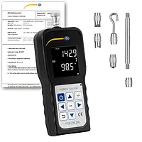
Sample calibration certificates for comparison
ISO 9001 with 5 individual measurement values each: ascending or descending for tensile and compressive force, as well as difference between actual and nominal values.
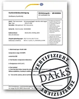
DAkkS with 6 test series each for tensile and for compressive forces, several installation positions and specification of extended measurement uncertainty.
Calibration certificate according to DAkkS
for a force gauge PCE-DFG N 5K with the measuring range 1 kN
Calibration certificate according to ISO 9001
for a force gauge PCE-DFG N 1K with the measuring range 1 kN

For the customers who need a DAkkS calibration for their force gauge, the PCE force measurement laboratory offers DAkks calibrations in cooperation with partner laboratories. Details about the test procedure and test conditions will be agreed on an order-related basis in the course of the preparation of the offer.
If there is no sufficient resistance to force, it causes deformations, movements or accelerations. With a suitable force gauge, the force can be determined based on its effect. Usually, the force is measured via the elastic deformation of a special spring body. The higher the nominal load, i.e. the maximum load for the force gauge, the higher the stiffness of the spring body must be. The amount of force to be measured should therefore be estimated before the measurement, so that the sensor from the force gauge is not destroyed by overloading. For a correct measurement it is important to consider the type of the acting forces, their direction and the environmental conditions and to choose the appropriate force gauge for this purpose.
If two groups measure their forces in a tug-of-war, the winner is the group that manages to pull the other group over a defined line towards it. However, the result of this "pulling force measurement" is not a reproducible numerical value that can be compared with the results from other measurements. The situation is different with the "Hit Lukas" force measuring device popular at funfairs. There, the force of the hammer blow, which acted vertically on the target point, can be read off a scale. The higher the force applied with the hammer is, the further up the metal disc lying on the other side of the seesaw rises. When it reaches the limit, there is even an acoustic alarm.
Force gauge assemblies
A force gauge always includes the force transducer, which is changed when force is applied, and a value output in the form of a readable display or a standardized interface for transmitting the measurement signal. In most cases, a further assembly is required between the sensor and the output unit for converting and amplifying the actual measurement signal. Additional components can increase the range of functions or the safety of use of the force gauge, for example overload protection, measured value memory or alarm transmitters. If high forces are to be measured, it is possible to arrange several force transducers in parallel and evaluate them together.
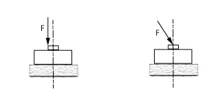
Do not use force gauges at angles – observe load direction
Due to the type of the force transducer, many force gauge models may only be loaded along the intended axis. If the force gauge is not loaded centred in the direction of the measuring axis, but at an angle to it, the amount of the total force cannot be determined correctly. Only the force component that runs along the measuring axis is determined. The additional load in a direction deviating from this can damage the force transducer if it is not structurally stabilized against transverse forces.
When using test stands and testing machines for force measurements, the load direction is fixed. However, care must be taken to ensure that the force gauge, test specimen, and test setup accessories are arranged and fixed according to the test requirements.
Example sketches of incorrect force application in a load cell, load applied off-centre on the left and applied centrally but not axially on the right.
For some force measurements, it is not possible to ensure that the entire force is applied in the intended measurement direction. For these applications, the force gauge should be used whose load cell is tolerant of extraneous loads. This insensitivity to extraneous forces can be achieved by the measuring principle or, in the case of the strain gauge force sensors, by special designs of the spring body. Information on the limit bending moment, limit torque and limit lateral force of the force sensor indicates how high the additional loads may be. If these sensor-specific values are exceeded, the sensor can be irreversibly damaged.
Use force gauges only in suitable environmental conditions
The force gauge can only function as intended if it is used in suitable environmental conditions. It is generally known that excessive humidity has a negative effect on electronic and other humidity-sensitive components. High humidity can cause condensation and thus both corrosion and leakage currents. Therefore, one of the most common operating conditions specified for measuring instruments, in addition to temperature, is the relative humidity.
When it comes to temperature influence, it is important to know that it is not enough for the force gauge to maintain the specified temperature range. In order to achieve precise measurement results, it is also necessary to prevent larger temperature differences from occurring on the sensor body because it is heated or cooled on one side during the measurement.
For measurements in areas where the force gauge is exposed to splash water or other liquids, or where many particles in the air are to be expected due to the process, the force gauge whose housing has a high IP protection rating is recommended. Special care must be taken with sea air, corrosive gases and vapours. In these cases, care should be taken to ensure that the installation is as protected as possible, and the force gauge used should be checked regularly.
Electromagnetic fields and vibrations from the environment are also among the frequently occurring interference factors. Depending on the type of the force transducer and its mounting, they can falsify the measurement result to a greater or lesser extent. If they cannot be avoided, these interferences should be considered when planning the measurement setup so that they have only a minor influence on the force gauge during the measurements.